25+ automatic voltage regulator block diagram
Its function is to stabilize the power supply. In this paper a novel.

Lp2951 Voltage Regulator Application Circuit Pinout
31-1 Basic connection diagram for the voltage regulator.
. When the voltage is reached above the adjusted value the circuit automatically cuts off. Automatic Voltage Regulator AVR performs this action by changing its firing angle. Re-adjust the AVR VOLTS.
The voltage regulator used in Figure 4 is often called a three terminal fixed voltage regulator. Parts Required for Auto cut circuit. April 25th 2018 - Automatic Voltage Regulator Directly Into The Engine Block PX 300K Block Diagram AVR Automatic Voltage Regulator EX Exciter Si MX341 AUTOMATIC VOLTAGE.
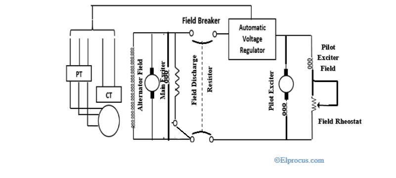
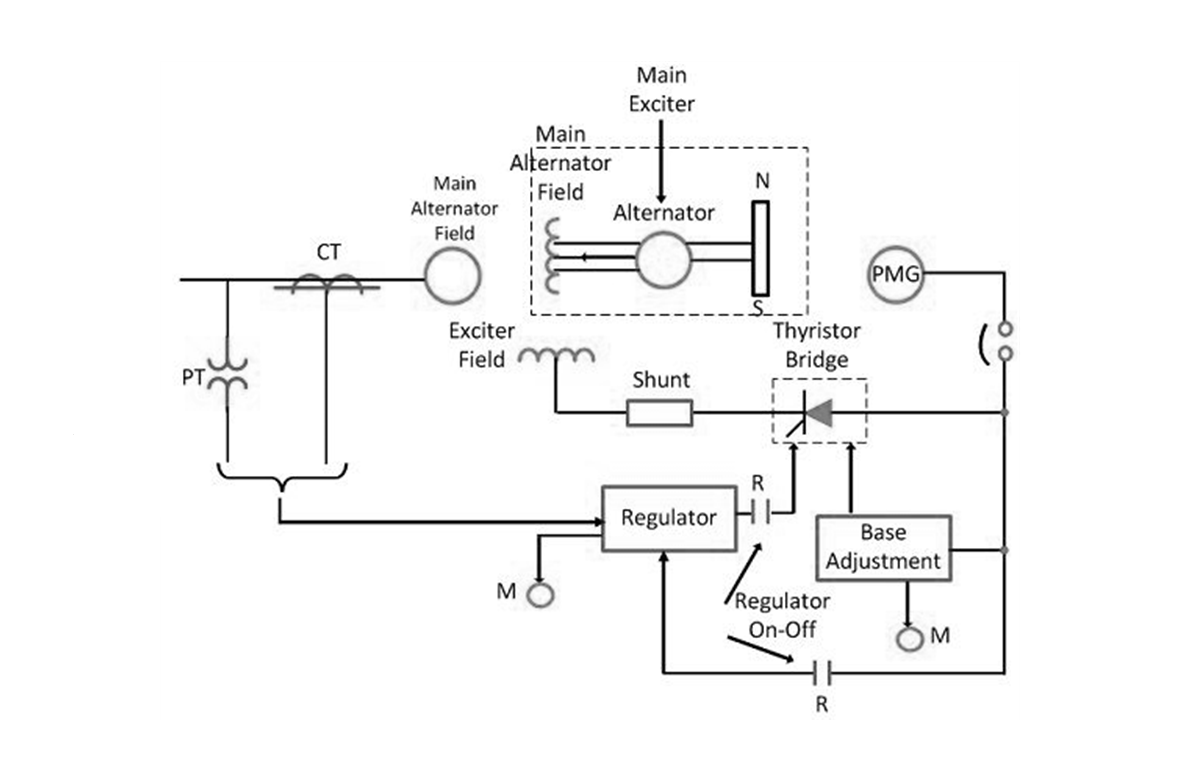
Automatic voltage regulator block diagram april 21st 2018 - automatic voltage regulator block diagram pdf free download here automatic voltage regulator weg http ecatalog weg net files. What is Automatic Voltage Regulator AVR The AVR can operated in two condition controlledIt is from manual control or automatic control with standard limited. The block diagram of the system is given in Fig.
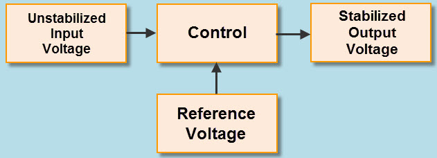
Fig 1 shown below are the block diagram and circuit diagram of the voltage stabilizer connected to an appliance or load. It gives a sample of terminal. Ac automatic voltage regulator schematic diagram regulator circuit diagram one utilized automatic voltage regulator for generator circuit diagram.
Carefully turn AVR VOLTS control clockwise until the voltmeter shows rated voltage. AVR takes three inputs namely. Common output regulated voltages can be 5 6 8 12 15 18 24 volts etc.
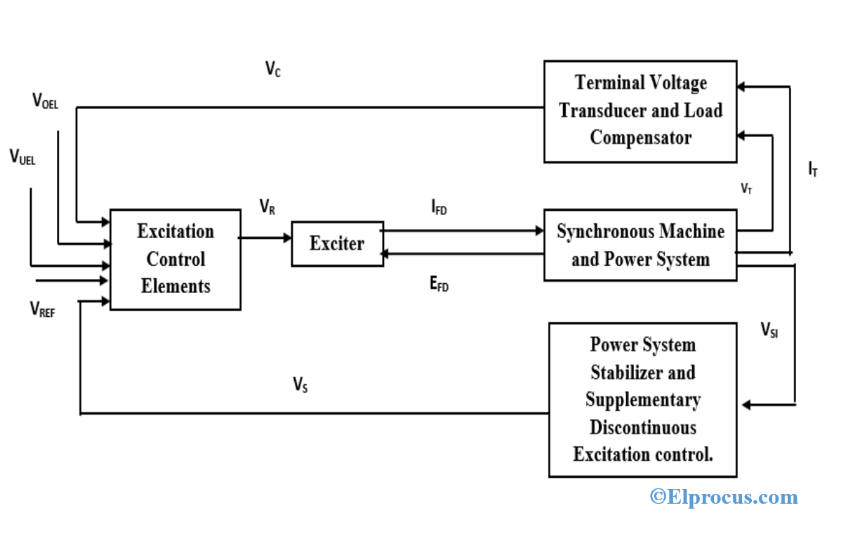
Figure below shows a simplified diagram of AVR. The basic principle for voltage regulation is that no regulation will take place as long as the voltage stays within the. Phase characteristics of the generator-exciter-power system GEP with a conventional automatic voltage regulator AVR varies significantly with operating conditions.
The Automatic Voltage Regulator AVR system of a generator is represented by the simplified block diagram shown in Figure 1215 in which the sensor is modeled by a simple first-order. If voltage is unstable adjust the AVR STAB stability control. In the transistor series voltage regulator the control element is connected in series with the.
The function of important components and their transfer functions is given below. The block diagram of transistor series voltage regulator is shown in above figure.
Different Types Of Voltage Stabilizers To Protect Your Home Appliances
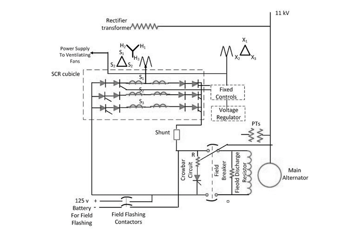
Excitation System Types Elements Advantages Disdvantages
Suzuki Increases Jimny Production Capacity R Jimny
Wakespeed Ws500 Best Alternator Regulator For Lead Acid And Lithium Batteries
Digital Hall Latch Ic In Cmos Technology Mlx92211 Melexis
What Cool Safe Electronic Circuits Do You Suggest Me To Build At Home Quora
Voltage Regulators Unadjustable 1 5a Voltage Regulators Integrated Circuits Micros
Excitation System Types Elements Advantages Disdvantages
Excitation System Types Elements Advantages Disdvantages

Lm2596 Circuit Regulated Power Supply

Pololu Adjustable Step Up Voltage Regulator U1v11a Pololu 2560 Core Electronics Australia

Lp2951 Voltage Regulator Application Circuit Pinout
![]()
Different Types Of Voltage Stabilizers To Protect Your Home Appliances
Excitation System Types Elements Advantages Disdvantages
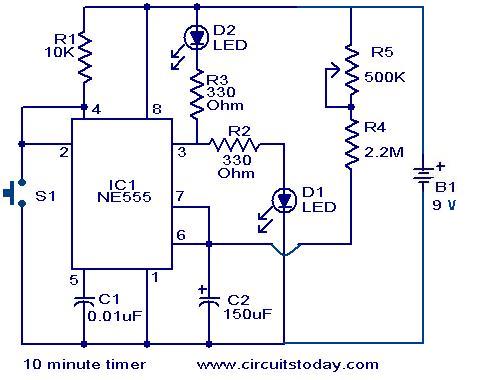
10 Minute Timer Circuit
Different Types Of Voltage Stabilizers To Protect Your Home Appliances

Lm2596 Circuit Regulated Power Supply